Instruction manual of M-6006 input module
2.Built-in product ID code
3.Using hardware and software filtering technology to improve the module's anti-jamming capability
4.Linkage, 2 bus type,nonpolarity
Figure 1 M-6006 Dimensions and installation dimensions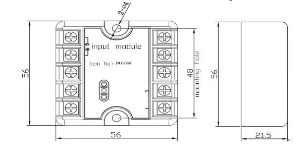
Figure 2 concealed wire diagram Figure 3 exposed wire diagram
2. wiring method shows in Figure 4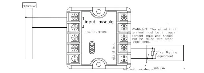
Figure 4: M-6006 wiring diagram
3. Wire requirements: Wire (bus) should be RVS-2 * 1.0 mm2 or 1.5 mm2; RVS-2*1.0 mm2 or 1.5 mm2 for signal input wire.
E. Use and operation
Encoding operation: you can use our company's hand-held encoder M-6006 to live coding. When encoding, connect the two clips of the encoder to the two terminals of the linkage, open the handheld encoder power, enter the address code to be written (address code range must be: 1-242, the address code for the same loop is unique). Press the "write code" button, if encoding is successful, the encoder will display the address number after sending the address code. If failed, the encoder will display "FAL" after sending the address code.
For details on the steps and methods of encoding, refer to the "M-6006 Handheld Encoder User's Manual".
.
2. When the controller detects the cleaning forecast, please send the number of smoke detectors back to the company for cleaning, in order to avoid false or false positives, resulting in unnecessary losses.


A. Features
1.Installed directly in the embedded box2.Built-in product ID code
3.Using hardware and software filtering technology to improve the module's anti-jamming capability
4.Linkage, 2 bus type,nonpolarity
B. Specifications
| Working voltage | linkage 15-28V Impulse voltage | |
| Working current | Standby current | ≤0.55mA |
| action current | ≤5.5mA | |
| Type | Addressable, 2 wire(nonpolarity) | |
| Encoding | Electronic code | |
| Module's Indication status | Normal monitoring status | The green inspection lamp flashes periodically |
| action state | red action light keep lit, green inspection lights keep lit | |
| Operating environment | Temperature-10ºC~50ºC Relative humidity≤95%RH,No condensation | |
| Dimensions | 56mm×56mm×21.5mm(transparent cover not included) | |
| Color | beige | |
| Weight | about 53g(transparent cover included) | |
| Executive standard | GB 16806-2006 | |
C. Structural features
1.Module's Dimensions and installation dimensions shown in Figure 1Figure 1 M-6006 Dimensions and installation dimensions
D. Installation
WARNING: Before installing the device, the power must be switched off.- The module can be installed in either a exposed way or a concealed installation. As for concealed installation, the module can be installed in the 86H50 standard embedded box, and then installed on the cover just like Figure 2 shows; for exposed way, the module installed in the terminal box which shown in Figure 3.
Figure 2 concealed wire diagram Figure 3 exposed wire diagram
2. wiring method shows in Figure 4
Figure 4: M-6006 wiring diagram
3. Wire requirements: Wire (bus) should be RVS-2 * 1.0 mm2 or 1.5 mm2; RVS-2*1.0 mm2 or 1.5 mm2 for signal input wire.
E. Use and operation
Encoding operation: you can use our company's hand-held encoder M-6006 to live coding. When encoding, connect the two clips of the encoder to the two terminals of the linkage, open the handheld encoder power, enter the address code to be written (address code range must be: 1-242, the address code for the same loop is unique). Press the "write code" button, if encoding is successful, the encoder will display the address number after sending the address code. If failed, the encoder will display "FAL" after sending the address code.
For details on the steps and methods of encoding, refer to the "M-6006 Handheld Encoder User's Manual".
.
F. Note
1. The alarm function test of smoke detector should be performed every six months.2. When the controller detects the cleaning forecast, please send the number of smoke detectors back to the company for cleaning, in order to avoid false or false positives, resulting in unnecessary losses.